HLR_V1: Arduino Line Follower Bot
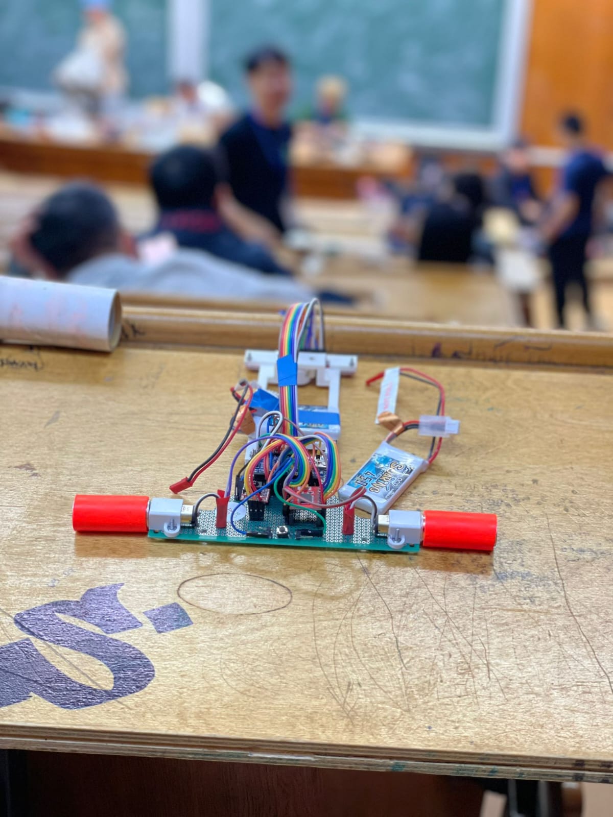
Welcome to the tutorial for HLR_V1, a fast line follower robot built on an Arduino Nano with Pololu QTR8A sensors, a TB6612FNG motor driver, and high-performance micro motors. This robot recently earned 23rd place internationally at the RoboChallenge Line Follower category.
In this guide, you'll learn how to assemble, wire, calibrate, and program your own line follower robot. We will cover the detailed hardware components (with images and technical data), wiring setup, an in-depth algorithm explanation, and tips for tuning the PID parameters.
Components & Materials
Below is a table of the main parts used in building HLR_V1. For each component, technical data, a sample image, and a short description are provided.
| Component | Image | Technical Data | Description |
|---|---|---|---|
| Arduino Nano | ![]() |
16 MHz clock 5V Operating Voltage 32 KB Flash Memory |
The main microcontroller board providing processing power and I/O for the robot. |
| TB6612FNG Motor Driver | ![]() |
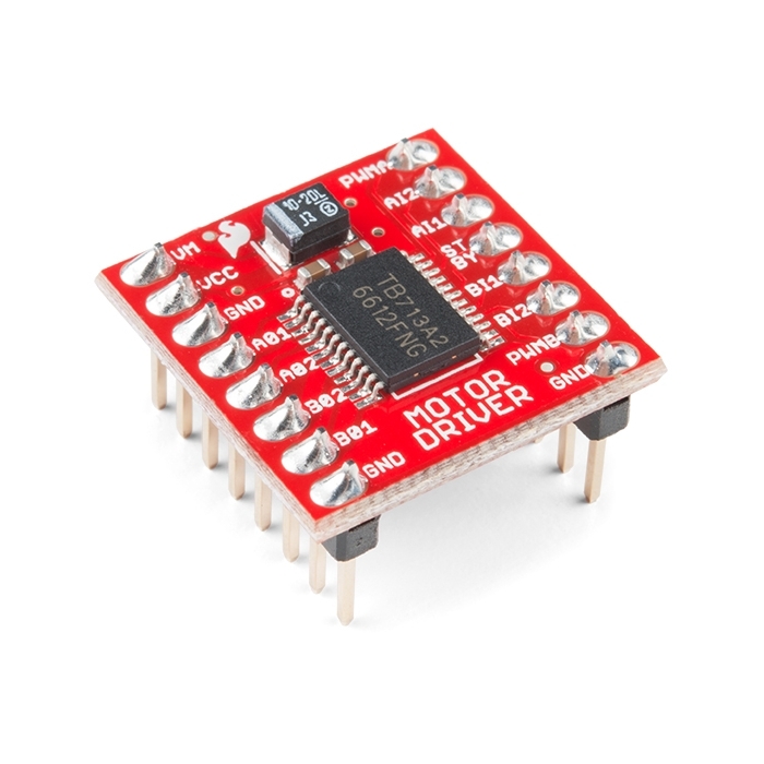
Operating Voltage: 4.5-13.5V Peak Current: 3.2 A |
Controls the DC motors by providing the necessary drive currents in both directions. |
| Pololu QTR8A Sensor Array | ![]() |
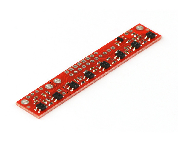
Analog Output (0-1023) High Resolution |
Provides accurate line detection by measuring the reflectivity of the surface beneath the robot. |
| Pololu MicroMotor 10:1 HPCB 6V | ![]() |
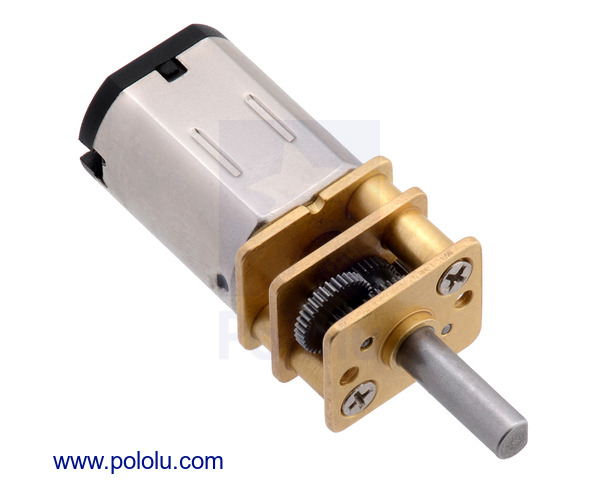
High Torque 10:1 Gear Ratio |
Drives the robot with high torque and precision after reduction. |
| 2S (7.4V) 450mAh LiPo Battery | ![]() |
Capacity: 450mAh High Discharge Rate |
Supplies power to the entire system, ensuring stable voltage levels for both the Arduino and motors. |
| JSumo Start/Stop Module | ![]() |
|
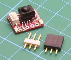
Provides an intuitive method to start and stop the robot during testing and competition. |
| JS2042 Silicon Wheels |
|
Ensures grip and stability while navigating challenging courses. |
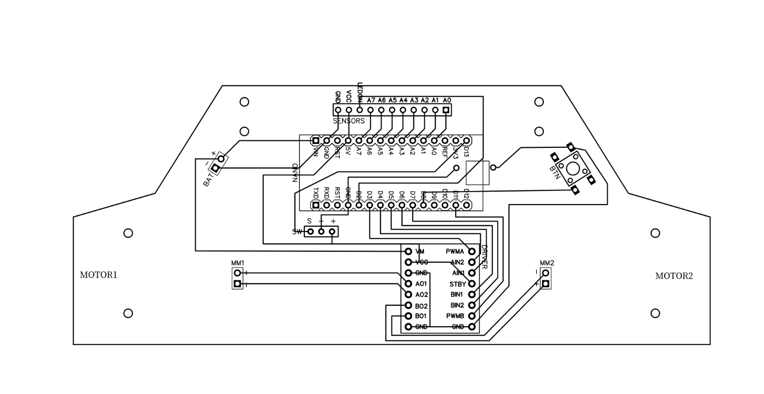
Wiring & Setup
Follow the wiring instructions carefully to connect all components correctly. The diagram below illustrates how the Arduino, sensor array, motor driver, and motors are interconnected.
-
Connect the QTR8A sensor array to analog pins
A0 through A7 on the Arduino Nano.Use a digital pin (e.g.,
D2) on Arduino to power the QTR emitters.
Wire the TB6612FNG motor driver:
AIN1 → D5, AIN2 → D4, PWMA → D3
BIN1 → D6, BIN2 → D7, PWMB → D11
Optional:
STBY may be tied high or connected to D9 for standby control.
Connect the motors to the motor driver outputs.
Power: Connect the 2S LiPo battery (7.4V) to the VIN of the motor driver, ensuring proper voltage for both Arduino and motor driver.
Double-check all connections and polarities before powering the robot. Incorrect wiring may damage components.
Arduino Code & Explanation
This section details the code powering HLR_V1. The program continuously reads from the sensor array to determine the position of the line and applies a PID controller for corrective steering.
Algorithm Overview
The robot’s control algorithm works as follows:
-
Sensor Reading: The QTR8A array provides analog values from eight infrared sensors. These values are processed to compute the
position of the line.
Error Calculation: The error is determined by subtracting the desired center (middlepoint) from the current position.
PID Control:
-
P (Proportional) adjusts the correction in proportion to the current error.
I (Integral) accounts for past errors (accumulated drift) for steady-state accuracy.
D (Derivative) anticipates future error based on the rate of change, helping to dampen oscillations.
Additionally, the code handles emergency corrections if the robot deviates too far from the line by initiating immediate corrective maneuvers.
/*
* Fast Line Follower Code - HLR_V1
* Competing in RoboChallenge 2023
*
* PID Tuning:
* Kp = 0.3
* Ki = 0.001
* Kd = 10
*
* Author: P. F. Andrei
* Last update: 4th November, 2023
*/
#include
#include
// Pin definitions
const int BUTTON_PIN = 8;
const int startpin = 13;
// Motor driver pins (TB6612FNG)
#define AIN1 5
#define AIN2 4
#define BIN1 6
#define BIN2 7
#define PWMA 3
#define PWMB 11
// #define STBY 9
// QTR array definition
QTRSensors qtr;
const uint8_t SensorCount = 8;
uint16_t sensorValues[SensorCount];
// Custom min/max thresholds for each sensor (optional override)
const uint16_t minThreshold[SensorCount] = { 35, 35, 35, 35, 35, 35, 35, 35 };
const uint16_t maxThreshold[SensorCount] = {905, 905, 905, 905, 905, 905, 905, 905};
// PID constants
#define KP 0.3
#define KI 0.001
#define KD 10
uint16_t position = 3500;
int P, I, D;
int basespeed = 230;
int speedp = 250, speedn = -240; // quick-turn speeds
int error = 0, lastError = 0;
int middlepoint = 3500;
int debug = 1; // set to 0 to enable Serial debugging
int calibration = 0; // set to 0 to run auto calibration routine
void setup() {
pinMode(startpin, INPUT);
pinMode(BUTTON_PIN, INPUT_PULLUP);
// QTR sensor initialization
qtr.setTypeAnalog();
qtr.setSensorPins((const uint8_t[]){ A0, A1, A2, A3, A4, A5, A6, A7 }, SensorCount);
qtr.setEmitterPin(2);
delay(500);
// Motor pins
pinMode(PWMA, OUTPUT);
pinMode(AIN1, OUTPUT);
pinMode(AIN2, OUTPUT);
pinMode(PWMB, OUTPUT);
pinMode(BIN1, OUTPUT);
pinMode(BIN2, OUTPUT);
// pinMode(STBY, OUTPUT);
// Button press #1 - Calibration
while (digitalRead(BUTTON_PIN) == 1) {
// Wait for user input to start calibration
}
// Auto swinging calibration routine
if (calibration == 0) {
for (uint16_t i = 0; i < 100; i++) {
qtr.calibrate();
}
delay(1000);
for (int c = 0; c < 5; c++) {
for (int i = 0; i < 10; i++) { motors_move(0, -200); delay(21); motors_move(0, 0); qtr.calibrate(); }
for (int i = 0; i < 20; i++) { motors_move(0, 200); delay(20); motors_move(0, 0); qtr.calibrate(); }
for (int i = 0; i < 10; i++) { motors_move(0, -200); delay(21); motors_move(0, 0); qtr.calibrate(); }
}
motors_move(0, 0);
}
// Button press #2 - Start
while (digitalRead(BUTTON_PIN) == 1 && digitalRead(startpin) == 0) { }
delay(2000); // brief countdown before starting
}
void loop() {
position = qtr.readLineBlack(sensorValues);
error = position - middlepoint;
// Emergency quick corrections when off track
if (position <= 1000) {
inert_stop();
motors_move(speedp, speedn);
} else if (position >= 6000) {
inert_stop();
motors_move(speedn, speedp);
}
while (position < 1000 || position > 6000) {
position = qtr.readLineBlack(sensorValues);
}
// PID calculation
P = error;
I += error;
D = error - lastError;
lastError = error;
int motorspeeddif = P * KP + I * KI + D * KD;
// Constrain the speed differential
if (motorspeeddif > basespeed) motorspeeddif = basespeed;
if (motorspeeddif < -basespeed) motorspeeddif = -basespeed;
// If nearly centered, run motors at a fixed near-full speed.
if (position >= 3300 && position <= 3700) {
motors_move(240, 240);
} else {
if (motorspeeddif < 0)
motors_move(basespeed, basespeed + motorspeeddif);
else
motors_move(basespeed - motorspeeddif, basespeed);
}
// Button press #3 - Stop operation
if (digitalRead(BUTTON_PIN) == 0) {
motors_move(0, 0);
while (1); // Halt further action
}
}
void inert_stop() {
motors_move(-250, -250);
int startTime = millis();
while (millis() - startTime < 25) {
motors_move(-250, -250);
}
}
void motors_move(int leftMotorSpeed, int rightMotorSpeed) {
if (leftMotorSpeed >= 0) {
digitalWrite(AIN1, HIGH);
digitalWrite(AIN2, LOW);
} else {
digitalWrite(AIN1, LOW);
digitalWrite(AIN2, HIGH);
leftMotorSpeed = -leftMotorSpeed;
}
analogWrite(PWMA, leftMotorSpeed);
if (rightMotorSpeed >= 0) {
digitalWrite(BIN1, HIGH);
digitalWrite(BIN2, LOW);
} else {
digitalWrite(BIN1, LOW);
digitalWrite(BIN2, HIGH);
rightMotorSpeed = -rightMotorSpeed;
}
analogWrite(PWMB, rightMotorSpeed);
}
Calibration & Tuning
Proper sensor calibration is essential for accurate line following. In our code, the auto calibration routine swings the robot to gather the extreme reflectance values from the floor. Adjust the number of iterations and delay timings based on your track surface.
PID Tuning Tips
-
KP (Proportional): Reacts to the current error. Too high may induce oscillation.
KI (Integral): Compensates for accumulated errors. Adjust slowly to avoid overshoot.
KD (Derivative): Reduces rapid changes. A higher value smoothens the control but may slow response time.
Experiment by adjusting these values to achieve the best balance between responsiveness and stability on your specific course.
Performance & Future Upgrades
HLR_V1 achieved an impressive 23rd place in the international RoboChallenge Line Follower Kids edition. The baseline performance from this design allows room for enhancements in both hardware and software.
-
Downforce Fans (EDF): Improve traction on the track.
Faster Motors/Gearbox: Reduce lap times with upgraded speed components.
Enhanced Algorithm: Further tune the PID controller or consider predictive control techniques.
Custom PCB: Streamline wiring and improve reliability.
Continue to experiment with both mechanical modifications and algorithm optimizations to push performance further.
The End
Congratulations! You now have a comprehensive guide to building and programming the your first Arduino-based line follower robot. Use this tutorial as your foundation for future robotics projects and competitions.
© 2025 - 2025 HyperLine Robotics. All Rights Reserved.


